
Yes, as I said - I do NOT mean lactobacillus rhamnosus… Just read the message
- 2 Posts
- 10 Comments
Joined 1 year ago
Cake day: July 15th, 2023
You are not logged in. If you use a Fediverse account that is able to follow users, you can follow this user.
To be clear - I do not mean lactobacillus rhamnosus.

 1·25 days ago
Even if we were to accept that at face value, it does not change the fact that libraries are paid for by taxes, which was my exact statement. My point was not what you seem to interpret in any case. My point, if any, was that we get a lot of really cool stuff for taxes… And also that, as most other things, they are not actually free.
I would say this map is wrong. The Danish Rip, Rap & Rup, is just as much onomatopeya as the Italian or Dutch.

 1·5 months ago
Thanks again for looking at this!
The NTC meassures very low ohm, in circuit it’s around 14 ohm.
The markings on the “receiver” board are: +27v, gnd, -27v and “mute”.
I would like to try to do some “divide and conquer” debugging, as the total number of components is rather low. I would like to try to eliminate the different “blocks”. Like I can connect it up, and measure the voltage after certain “stages”. Maybe after the inrush current limiter? To my very limited understanding that should be right at the end of the AC block/stage? Maybe dividing the board into 3 or 4 stages like this I could start to narrow down the issue?
I am guessing the MOV is the component marked MOV on the board, its markings are: TVR 07471. Can I test this "in-circuit, or must I de-solder it to test it?
In-Circuit I measure around 470kohm
Thank you for taking the time to help out :-)
I have attached a couple of images. I figured the PSU is the issue, since there is 0v between the black lead and the other leads on the connector to the other parts - the one in the bottom right corner on the attached overhead.
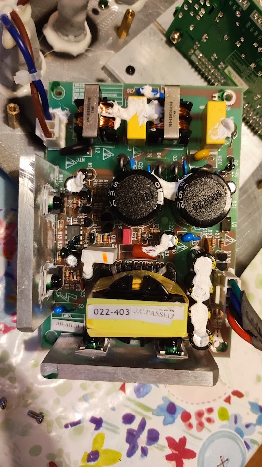
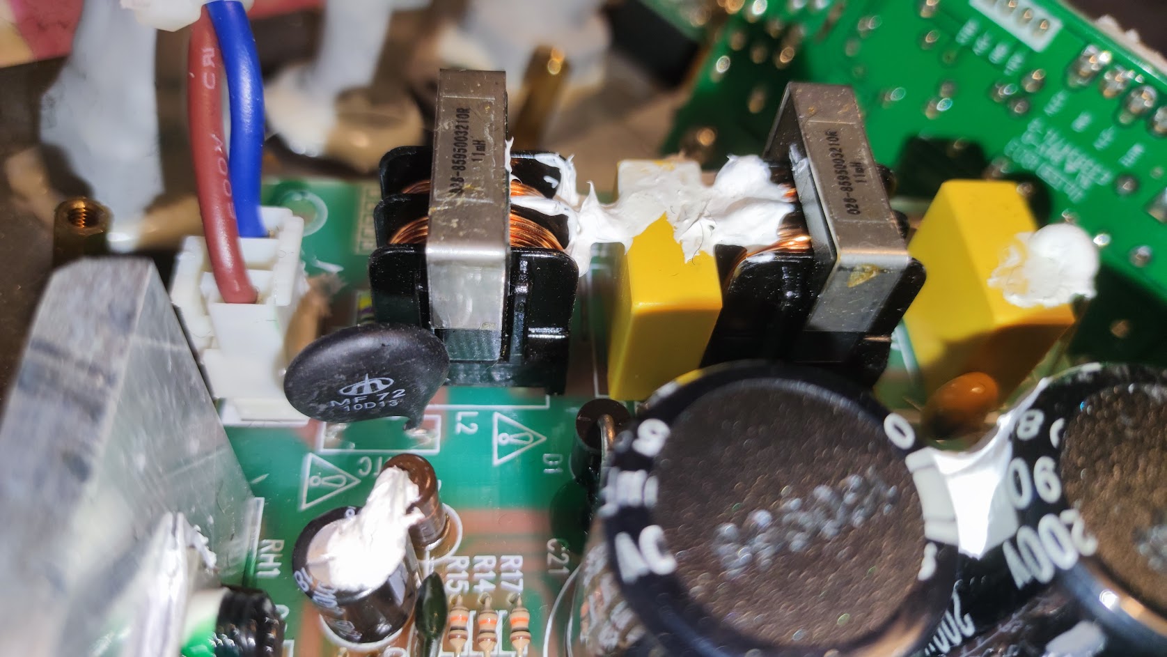
I measured the “MF 72 10D13” for connection, and it is OK. I then measured the two large capacitors (in-circuit) and they both come out fairly close to the 390uF they are rated as. I also tried to measure what I think are 4 transistors attached to the heatsinks. But am uncertain of the results there, as I can’t follow enough of the circuit to understand the results - and I am not even sure they are transistors - much less if they are npn or pnp :-) They are marked as Q1, Q2, D6 and D7 on the board.
When visually inspecting the board and components, the only thing I thought, might be “odd” was the “browning/darkening” around the circuitry near where “R1” is located.
Pigs can’t look up? Hahaha WTF? Who came up with that?
Thanks for having a look. Yeah it’s because of the paper. I dug into the source and the research they cited, and it sounded a lot like lactulose was pretty much ineffective at promoting any of the really beneficial bacteria. And the price for chemical grade Rhamnose is way beyond my budget, especially as, as far as I could tell, the dosage is pretty high, to get the benefits.