Hello, thanks in advance for any help. I have a little project I am trying to do-- I would like to merge a “Mag quadsafe universal adapter” with a Galaxy Fold 3 case. I have both STLs and i began playing with blender yesterday, and it’s possibly a little above my head.
What it seems like the steps are from my (peprhaps simplistic) point of view:
- trim the openings on mag quad adapter to fit the camera lens and side buttons when it is perfectly centered on the case.
- delete a square the exact size of the magsafe quadlock adapter that is perfectly centered on the back of the phone case
- put the current model from the mag quad stl in thus square
The only thing I’ve been able to accomplish thus far is centering the mag quad adapter on top of the case. I cannot, for the life of me, figure out how to trim in to fit the camera and side button openings…
Any help is greatly appreciated, even if it’s just a starting point.
You must log in or register to comment.
F you’re a beginner then I think my first advice to you is to not use Blender. Start with something like TinkerCad, much easier to work with, and more than adequate for what stated.
TinkerCad lets you add shapes together, and the neat thing is that there are also hole shapes, negative volumes that you can use to cut away material.
I tried with tinkercad, and I struggled. I was again able to align the shapes directly on top of one another, but when it came to modifying the actual shape I could not figure it out- is there a tutorial on adding shapes together or anything, or even carving stuff out?
I looked and couldn’t find anything this specific. It seemed like a much easier tool to use, but I couldn’t figure out how to do what I wanted. I also used
There are many YT channels about 3d printing that also cover TinkerCad. One of them is HL Modtech, this one for instance = https://youtu.be/gPeWdLQYfuA
Here is an alternative Piped link(s):
https://piped.video/gPeWdLQYfuA
Piped is a privacy-respecting open-source alternative frontend to YouTube.
I’m open-source; check me out at GitHub.
I’ll check it out. I liked tinkerCad when I used it, but it didn’t seem like there is a way to trim either object to do what I wanted, so I wasn’t sure if it’s the right tool. Maybe a little user error on my end, so I’ll look into it more
I didn’t check your other responses about the actual shapes you want to work on, but IMHO trimming away some edges or pieces is really simple, just by putting a “hole block” on the material you don’t want. Group the parts together and see the result.
I’m also a newbie that uses blender, which open source CAD tool would you recommend (if you have any experience with it)?
Don’t know any good open source. Use TinkerCad…
So, out of the box, blender is not a cad tool and it’s not a good option for anything that requires any amount of precision- there are extensions that will help, I’d just as soon suggests any other cad tool.
That said, if you can, link the files you’re using and the, we could give give you a more precise work flow.
https://www.thingiverse.com/thing:4935721 (right cover stl) and https://www.thingiverse.com/thing:5704716 are the two files I’m trying to merge. I’m gonna try playing with windows 3d builder as someone suggested as well
The process is pretty simple. “difference”, “subtract” or “hole” (tinkercad. don’t ask me why they call it that.) all do the same thing. It’s a boolean operation that removes one shape from another shape.
you create the shape and subtract the middle bit (a square slightly smaller than the adapter part itself.) Then put the adapter centered in the gap, and use a second boolean operation (usually called “join”, tinker cad calls this “grouping”… don’t ask.)
Sometimes you’ll see a third option in there called ‘intersect’, which will cut both parts down to only where they overlap, FYI.
So the process is to import your files, remove the bits that need to be removed… then join the adapter to the case, and export as an STL. the reason it’s important that the block your using to remove is slightly smaller is so that the adapter joins in a solid manner.
if you’re willing to give tinker cad another go, this video, while basic covers everything you need to do to get it done.
ETA: I think you’re going to have difficulty printing the combined part. the case appears intended to print with the back against the bed. you might be able to print it on edge, but the adhesion is going to suck and the nozzle dragging is likely to pull it off. you could also add supports, but then… well… support removal.
Thanks- I’ll check it out! I liked how simple TinkerCAD felt, and was hoping to use it, if I can, that’d be awesome
Here is an alternative Piped link(s):
Piped is a privacy-respecting open-source alternative frontend to YouTube.
I’m open-source; check me out at GitHub.
I found windows 3d builder to be very beginner friendly for modifying basic shapes.
Thanks, I’ll look at it!
Do you have some pictures and drawing to explain what you want to achieve?
I agree with the comment about using something simpler than Blender. Blender is the right tool for organic shapes and for sculpting.
What I understand is that you have two models, one for a phone case, one of a “hole” for fixing a magnetic holder.
I use OpenSCAD. With this tool, this would be my logic (could be replicated in other tools :
- import the mag holder stl
- create a rough shape, like a cylinder, that would fill the hole
- make a “difference()” between the cylinder and the mag holder. This way, the cylinder has the shape of the complex hole. You can then use this shape to make a hole in the stl of the case
- import the case
- import the mag holder once again / or add a volume the shape you want
- use “difference()” between the case+mag holder and the complex hole shape to clear the hole
you can enhance this process by creating a negative shape of the buttons holes
Edit: This is as far as I got in Tinkercad/Blender/Automesh – I had trouble actually modifying the shapes in any way in all programs (I am an absolute beginner at this, but I wanna learn and have access to a few different makerbot printers):


This is my crude sketch on what I wanna do.

This is the magquad holder I want to integrate directly into the case.
I don’t wanna stick the holder on my naked phone, and if I put the holder on the case as it is, it will likely be too thick to charge.
OK that’s clear.
What I would do :
I would remove the corners of the mag holder.
For this, I would make a big cylinder to catch what I want, and use an “intersection” to get only the center.
https://piped.video/watch?app=desktop&v=Z3sgFGeoQTs . Try it first with a cylinder, but actually, I would use a cone or a really big sphere to have a chamfer.Then I would place my new shape like you on the case. Without the corners, you would not get the troubles of removing the complex shapes for the camera and the buttons.
I love this. This would make it easier. I can use the exact same cone to “cut” the case. I’ll also be able to perfectly center the cone on the mag quad adapter (not sure if the stl has is 100% centered or not, but this way I can get it perfect.
I’ll play with this. Probably won’t have time for a few days, my days are busy. I tried using sphere deletion in blender yesterday, and it was a bit tough since it was my first time using any 3d design software.
I think this is probably the best suggestion for how to accomplish this, and I’ll be able to focus on doing it soon.
Thanks! This sounds a lot, but I wanna try making it. I like modifying things to suit my use, and this sounds like a fun learning endeavor. I’ll perhaps look at OpenSCAD. This sounds similar to some of the information I found on blender (making shapes to delete areas). I need to play with these tools to get more facile at doing this.
I don’t have a picture readily availble at the moment, but the stls are https://www.thingiverse.com/thing:4935721 for the phone case (I just wanna use the right side) and https://www.thingiverse.com/thing:5704716 for the holder. It’s a little more complex than just a magsafe holder, it has a quadlock mount integrated.
Does something like this works for you?
https://drive.google.com/file/d/15lq4Fz3rzJdIM7iXbC3JB79-IPjsTIzY/view?usp=sharing
I just imported the 2 stls in blender put them together, like in the same place as you wanted
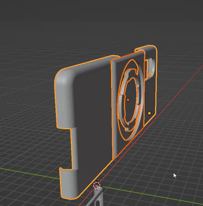
Selected both as seen in the image, then File -> export -> STL. Make sure you have “selection only”.
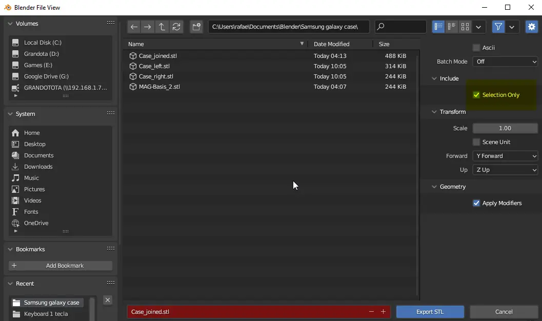
Export it, open it in your favorite slicer, and that should work.
Blender can do a lot, I use it to design and modify a lot of things from thingiverse too, and I have learned a lot of tricks on blender too.
I also want to learn freecad to do stuff from scratch, but in the meantime blender does what I need.
EDIT: Most probably I did not understand the requirement correctly, is this supposed to have a hole? hit me up if you want, happy to help https://discord.com/users/poringo#6290
Another Edit: Oh something like this?

Something like that last image is exactly what I’m trying to do! I probably could have described it better.
I think it’s probably a bit more complex than I thought, and I’m not sure it’s doable it tinkerCAD (i couldn’t find any way to trim objects…perhaps i’m just missing it). I’m gonna play with windows 3d builder soon when I get a chance I think.
If you can’t make it work with other programs you could do this with the boolean modifier in blender. I’ll give you a rough rundown of the necessary steps.
To cut the adapter to the right size you first create a cylinder that has the correct circumference and place it in the centre of the adapter. Then you select the adapter object and add a boolean modifier that should look like this.

You can then apply the modifier (by clicking on the small arrow in the upper right corner of the modifier card) and remove the cylinder again.
if you are happy with the result you can then move on to the next step. You could now merge the adapter again with a boolean modifier (although this time you have to select union) but if you want it to be recessed in the case you have to do another step first otherwise it would just fill the recess in the adapter model you have. You simply add another cylinder and scale it so it is slightly larger than the recess in the adapter and remove it from the case again by using a boolean modifier but with difference selected this time.
I hope this helps a bit. I know that if you don’t know blender this explanation won’t be enough to do this but if you have any questions then feel free to ask.
Prusaslicer has some pretty good stl manipulation tools built-in these days. You can merge, split, add common shapes, subtract shapes, etc.
From the outside looking in, it seems like you should be able to do everything you want right in the slicer.
I’ve found this to be preferable for working with existing stl’s (not as useful for editing) if you dont have the actual step files or 3mf files available.
New Lemmy Post: Merging two objects (I’m a beginner) (https://lemmy.world/post/9075839)
Tagging: #3dprinting(Replying in the OP of this thread (NOT THIS BOT!) will appear as a comment in the lemmy discussion.)
I am a FOSS bot. Check my README: https://github.com/db0/lemmy-tagginator/blob/main/README.md
If you want to use blender for this you should be able to use a boolean operation to combine the two bodies you import. Your computer should do the second step for you in any reasonable modeling software.