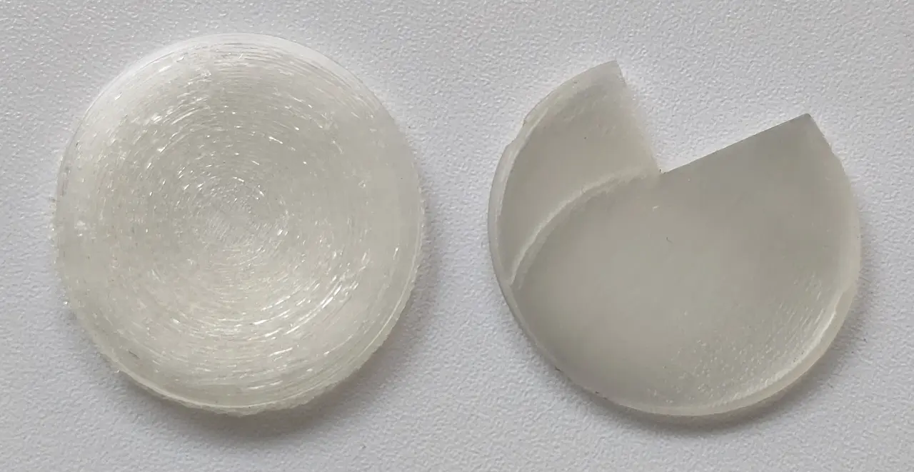
In the process of refining the design for my 3D printed glasses (yes, I’m still at it 🙂) and trying to streamline the lens ordering process a bit, because some folks have told me their optician, or their optician’s lens supplier, didn’t really want to mess with “unusual” things like this, I decided to draw and print a fake ophthalmic lens. You know, not optical-quality - or even see-through - but something that looks and feels like a lens, that can be mounted in my frames, to show an optician hands-on how it works and that it’s not weird or delicate to work on.
I figured it would be a quick print in clear PLA, that would require only a bit of cleanup and mount right into the frames, complete with the bevel and the notch and everything. How wrong I was…
This part is almost impossible to print right:
-
It’s modeled after a real bispherical lens with an offset optical axis. I mean it’s optically incorrect, but it has everything a real lens would have: uneven edge thickness, one convex and one concave side.
You just can’t set it flat on the bed in the slicer: none of it sits flat. The slicer has trouble generating support around the edge on the concave side that it interprets half of as overhang, and even if the beginning of the support doesn’t get ripped off by the head and the print completes, the surfaces will be absolutely awful.
-
If you print it vertical - which frankly is the least bad option - then the bottom of the lens, under the support, will be a complete mess. The bevel won’t even be visible. It takes quite some time to create supports that won’t mess up the bottom of the lens too much
-
If you print it in clear PLA with only perimeters, it’ll be transparent enough to see the spots were the perimeters are started at the next layer. And depending on your wall generation strategy, the spots where the printer tries to fill the voids will show up as round “halos” inside the lens.
The lens’ thickness varies everywhere, so the slicer tries its best to fill each layer, but it’s slightly different at every layer. At any rate, it reveals the slicer’s idiosyncracies in tool path stragegy right away.
-
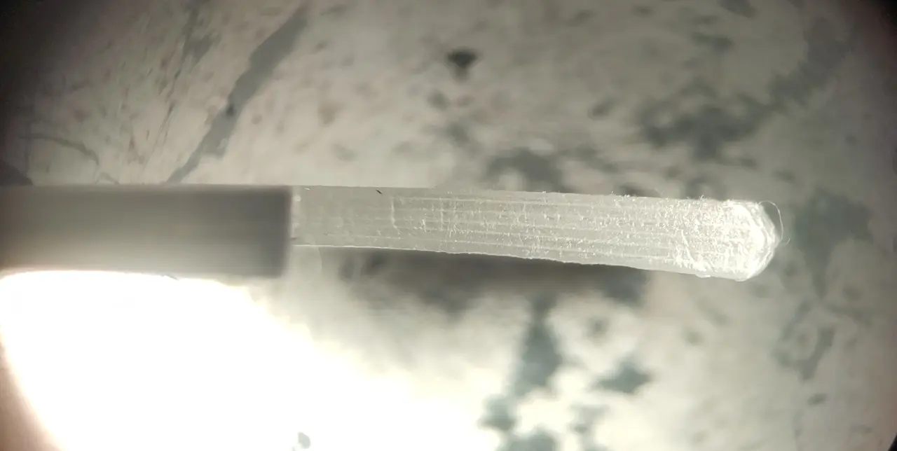
The bevel all around the lens is only 0.5mm high. If the printer is dialed in, the bevel will show as an actual 120-degree bevel near the front face of the lens, particular where the bevel is normal to the layer, about half-way up the lens if you print it vertically. If not, it will look like a barely-raised blob.
I’ve tried this print on 3 different printer and I just can’t get a decent print. All I can do is play with the settings in the slicer until it comes out not too terrible.
So, that part is a bit frustrating for my original purpose, but it turns out to be a great part to test a printer and/or the slicer software! If you want to try it too, it’s here:
https://github.com/Giraut/3D-printed_eyeglasses/raw/refs/heads/main/lens_example.3mf


Can’t argue with that. I still use FDM as well for a lot of models - currently running an old Ultimaker 2 and a BCN3D Sigma D25 for the bigger batch jobs.
The latter is mostly stock but the UM2 is pretty much unrecognisable from when it was new now; a real Ship of Theseus. Bigger gantry, uprated board/head/feeder and tweaked Tinker firmware to suit. Shoved a Pi with Octoprint in there too.
While you can get flex & specialty resins, you are right that you’re certainly not printing them alongside the regular stuff in one run like you intend to, unless the model is redesigned in multiple parts. They are also priced to suit :|
Will be good to see what you come up with. Almost all of my prints are the work of others these days. I’m not much of a designer and the furthest I go with CAD is putting terribleness together in a 12 year old version of Sketchup 😂